Retro-Emission
Relating to work conducted from 2008 to 2011
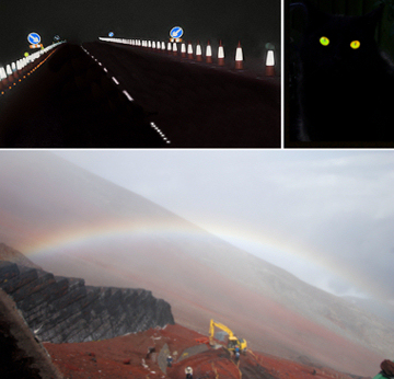 If you have ever driven at night you will know that road signs and cat's eyes etc all appear to shine brightly. If you have ever thought about it, you might have considered that this effect is only seen from inside the car: the signs do not appear bright if you are standing by the roadside, and that this effect is also not really visible at all during the day. The reason for this is that the shiny bits of the signs are made from a material known as a retro-reflector. This means that regardless of the angle of the incident light the reflector shines it back to where it came from. The analogy to this effect is when you hit a squash ball into the corner of the court. Here, you will see that the ball will hit two of the walls and regardless where you are standing will come straight back towards you. In fact, the road signs are specially built so that the light comes back at a slightly different angle so that the reflection of the car headlights reaches your eyes (the signs would appear dark to you if all the light was exactly reflected back to the headlight). As an interesting side note the reason real cat' s eyes appear to glow is that they also have reflectors behind their eyes, they do this so the light travels through the back of the eye twice so they can see better when it is dark.
This effect also works for small spheres and the earliest road signs used spheres for their reflective parts. A rainbow is also an example of this effect where the small spheres of water (rain) reflect the act to direct sunlight back to where it originated, this is why you only see a rainbow when the sun is behind you. This effect works differently for different colours and so they are split up, resulting in the rainbow.
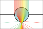
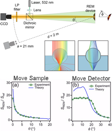 So, retro-reflection is very useful and hence it was decided to investigate the possibilities of retro-emission. This is where a sphere is used as a lens to focus the incident light to a small point within a fluorescent material, the same sphere then also efficiently collects the emitted light and collimates it. Thus, an array of spheres on a fluorescent material will act to channel the emitted light into a tightly confined beam. This could find applications for increasing the brightness of fluorescent surfaces, but we are more interested in using them to measure the light emitted from very weak sources. The materials of interest are novel in their own right and are known as nano-phosphorus. These are of interest because when excited with red light they emit in the green (normally it is the other way around). Because of this they are useful as they can be seen more clearly against a background of other material as no others will emit in the say way. Another interesting and related feature of these particles is that the amount of emitted light is related to the square of the intensity of the input light (normally it is a linear relationship). Thus, by focusing the incident beam to a higher intensity it will be possible to actually produce more emitted light, and so the sphere retro-emitter system helps three times, in the excitation, the collection and collimation of the emitted light.
The figure, right, shows the schematic of the set up and some test data from a normal fluorescent material covered with spheres. One of the first challenges was to write a simulation program that could take into account the light emitted from every point within the surface. As shown in the figure the theoretical traces fit very well with the experiments, making it possible to quickly simulate many situations to get a better understanding of how the retro-emitters behave. Note that, as expected, the emitted light (in the move detector plot) is very well collimated, forming an almost perfect beam at zero degrees. The other plot shows that the retro-emission effect works well for observation angles up to about 20 degrees (when both excitation source and detector are moved). This relates to the fact that throughout these angles the focal point behind the sphere is still within the fluorescent material, above 20 degrees the light is focused into the air and so there is little excited light. Hence, we can see that we have formed an effective retro-emitted.
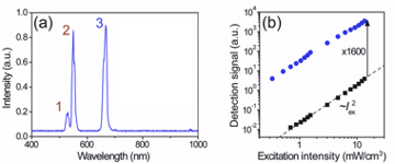 With this understood it is then possible to test the nano-phosphors. This is shown on the right. The particles used emit light between 500 nm and 700 nm, shown in (a), when excited with 900 nm light. As shown in (b) the amount of emitted light increases quadratically with the amount of excitation light (the graph is on what is known as a log-log plot where the slope shows the exponential increase, this case power 2). What is of real interest is the fact that the simple act of placing the correct spheres in the right place yields 1600 times increase in the detected signal. That is impressive in itself but theoretical calculations show that with further optimisation this figure could be even higher; hence being of real potential use to easily study single nano-particles or for other applications where increased signals and efficient beaming of the emitted light are of importance.
Papers relating to this work:
 Retroemission by lens arrays for high intensity, high contrast imaging of upconverting phosphors
B. Sandnes, T.A. Kelf, H. Liu, and A.V. Zvyagin
Opt. Lett.36, 3009 (2011)